
Whether you’re a first-year apprentice, a general contractor walking a new job site, or a homeowner trying to make sense of a renovation plan, blueprint literacy is one of the most useful skills in construction. Blueprints look intimidating at first — dense with lines, abbreviations, and tiny numbers — but once you know where to look and what the standard conventions mean, almost any set of construction drawings becomes readable. Here’s a practical, beginner-friendly breakdown of how professionals actually approach a new set of plans.
Before you trace a single wall, find the title block. It’s usually a dense rectangle in the lower right-hand corner of the sheet, and it functions as the blueprint’s ID card — telling you the project name, address, architect or engineer of record, sheet number, drawing date, revision history, and the scale the sheet is drawn at (BigRentz; Harris Constructors). Skipping the title block is one of the most common beginner mistakes — it takes thirty seconds and tells you exactly what you’re looking at and whether you have the most current revision.
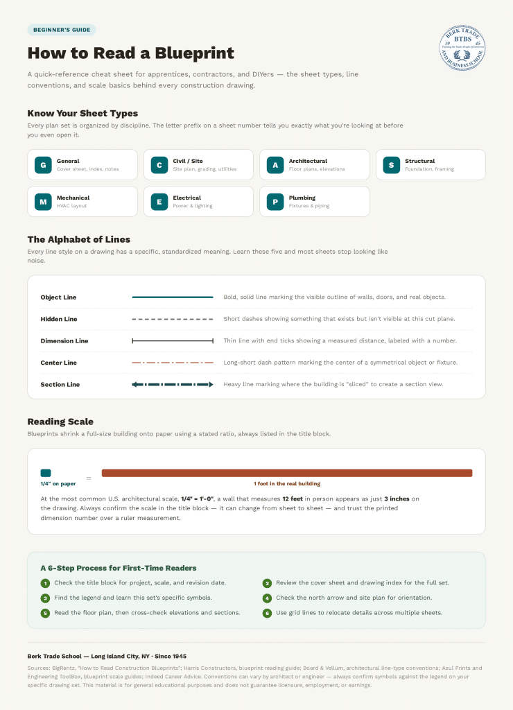
A full plan set can run anywhere from a handful of sheets for a small residential job to hundreds of sheets for a large commercial project, but nearly all of them follow the same discipline-based organization, identified by a letter prefix on each sheet number (PlanUpPro):
| Prefix | Discipline | What it shows |
| G | General | Cover sheet, drawing index, code and general notes |
| C | Civil / Site | Site plan, grading, utilities, property lines |
| A | Architectural | Floor plans, elevations, sections, door/window schedules |
| S | Structural | Foundation and framing plans, structural details |
| M | Mechanical | HVAC layout and equipment |
| E | Electrical | Power, lighting, and panel schedules |
| P | Plumbing | Fixture layout, supply and waste piping |
Always start at the “G” sheets — the cover sheet and drawing index will tell you exactly what’s included and point you to the right sheet for the trade or area you’re focused on.
Blueprints represent a full-size building on a sheet of paper, so every drawing is created at a stated scale — a ratio between a measurement on the page and the actual size of the object. In U.S. residential and commercial construction, the most common architectural scale is 1/4″ = 1′-0″, meaning every quarter-inch on the drawing equals one foot in the real building. A room that measures 12 feet wide in person would appear as 3 inches wide on that sheet (Azul Prints). Different sheets in the same set are often drawn at different scales — floor plans might use 1/4″ = 1′-0″, detailed wall sections might use a larger scale like 3/4″ = 1′-0″ for more clarity, and site plans typically use a smaller scale to fit an entire property on one page (Engineering ToolBox). The scale is always noted in the title block — check it on every sheet, since it can change page to page.
One important rule professionals follow: never measure a printed dimension with a ruler and assume it’s accurate. Printed and PDF-exported drawings can shrink or stretch slightly. Always use the written, numeric dimension on the page — if a needed dimension isn’t labeled, ask before assuming.
Construction drawings use a standardized “alphabet of lines,” where each line style has a specific meaning:
- Object (visible) lines — solid, bold lines that outline the actual visible edges of walls, doors, and other real objects.
- Hidden lines — dashed lines showing something that exists but isn’t visible at that cut plane, such as wall cabinets shown above a counter in a floor plan (Board & Vellum).
- Dimension lines — thin lines with arrows or ticks at each end, showing a measured distance, with the number placed directly on or above the line.
- Extension lines — thin lines that extend out from an object line to connect it to a dimension line, without touching the object itself.
- Center lines — long-short-long dashed lines marking the center of a symmetrical object, like a column or a fixture.
- Section lines / cutting-plane lines — heavy lines with arrows indicating where the building has been “sliced” to create a section view, and which direction you’re looking.
Once these six line types become second nature, most plan sheets stop looking like noise and start looking like a clear, layered set of instructions.
Learn to Read Common Symbols — Then Check the Legend
Doors, windows, electrical devices, and plumbing fixtures are all represented by standardized symbols rather than realistic drawings — a door is typically a line with a quarter-circle arc showing its swing path, an electrical outlet is a small circle with two short lines, and a light switch is a circle with an “S.” These conventions are broadly consistent across the industry, but every architect or engineer can adjust hatch patterns, abbreviations, or fixture symbols slightly. That’s exactly why every sheet includes a legend — always check it before assuming a symbol means what you think it means (Harris Constructors).
Plans communicate a three-dimensional building using a few standard two-dimensional views, and reading a set well means mentally combining them:
- Plan view — looking straight down at a floor, as if the roof (or the floor above) were removed. This is what most people picture when they hear “blueprint.”
- Elevation view — looking straight at a vertical face of the building, such as the front exterior or an interior wall, showing height, window and door placement, and finish materials.
- Section view — a vertical “slice” through the building along a cutting-plane line marked on the plan view, revealing what’s inside a wall, floor, or roof assembly (Board & Vellum).
A detail that looks confusing in plan view is often perfectly clear once you find the matching section or elevation — cross-referencing between views is a core blueprint-reading habit, not an optional extra step.
A Simple Step-by-Step Process for Beginners
- Check the title block for project, scale, and revision date.
- Review the cover sheet and drawing index to see what’s in the set.
- Locate the legend and learn the specific symbols used on this set.
- Check the north arrow and site plan to understand building orientation.
- Read the floor plan for layout, then cross-reference elevations and sections for anything unclear.
- Note any grid lines (lettered and numbered reference axes) so you can quickly relocate a detail across multiple sheets (Indeed).
- Always trust written dimensions over a ruler measurement on a printed or scaled page.
Where Blueprint Reading Fits Into Trade Training
Blueprint reading isn’t a standalone class most people take on its own — it’s a working skill built into hands-on trade training. At Berk Trade School, blueprint and plan reading is incorporated directly into both the Electrical Installation Program and the Comprehensive Plumbing Program, so students practice reading real plan sets alongside the wiring, piping, and code material they’re learning at the same time (Berk Trade School).
This article is for general educational purposes and does not guarantee licensure, employment, or earnings. Always follow the specific conventions, legend, and notes on the actual drawing set you’re working from, and confirm project-specific requirements with the architect, engineer, or contractor of record.